# 07:VLAN间路由
点此下载本次实验的 Cisco Packet Tracer 文件
# 实验要求
首先需要明确一点,不同的 Vlan 相互隔离广播域,因此,传统的以太网 ARP 方式的通信机制在这里是不可用的,需要在网络中添加三层设备,这里的三层设备可以是路由器,也可以是 Cisco 三层交换机(例如 Cisco 3550,Cisco3560)。
本次实验的目的,是让处于不同 Vlan 下的主机能够通信,因此用路由器充当上述的三层设备,需要用到的知识点有:
Vlan 的划分
VTP 同步
将接口划分进 Vlan
Trunk 链路的封装类型
子接口的配置
# 实验拓扑

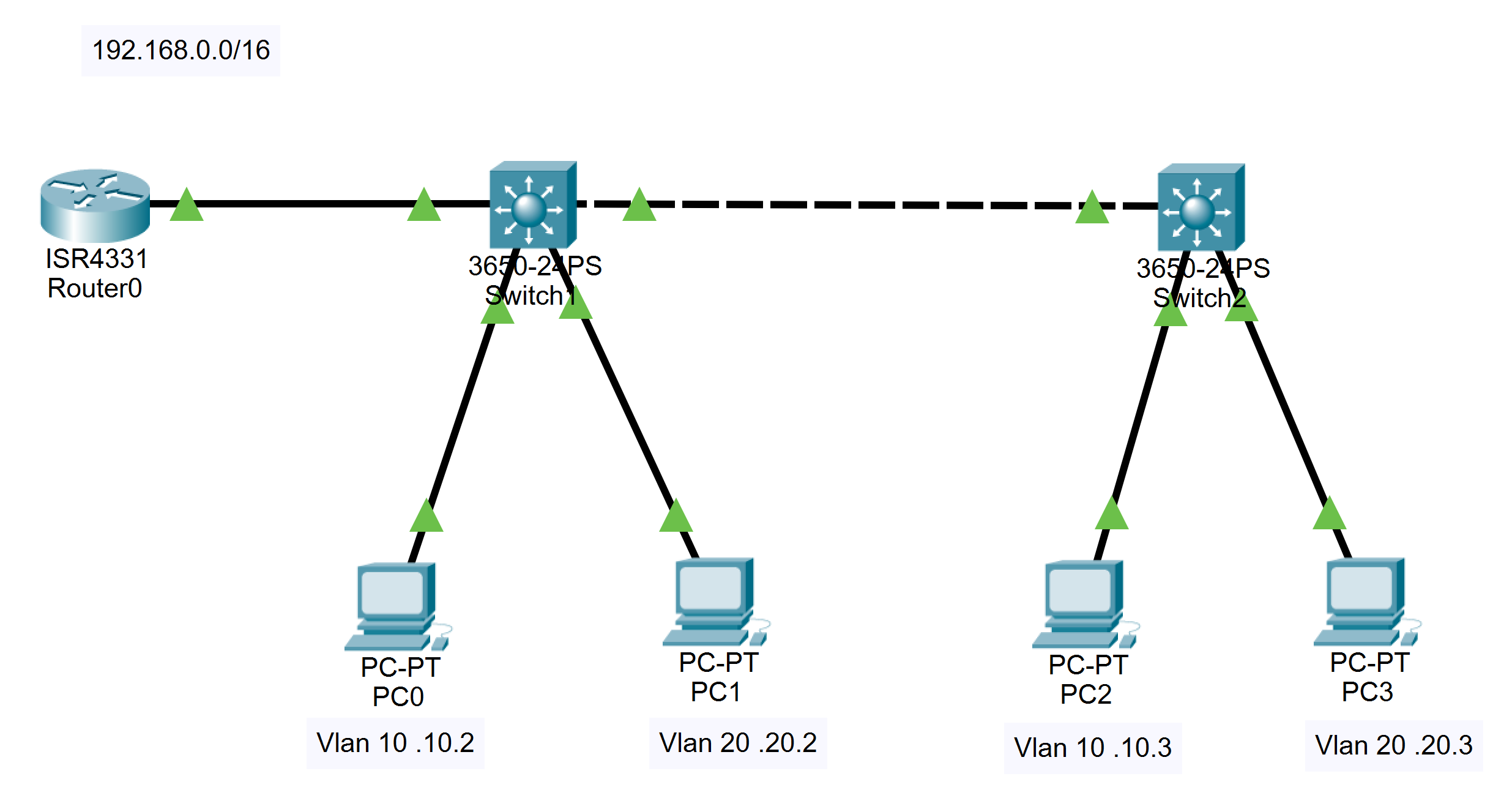
PC0 和 PC2 属于 Vlan 10,PC1 和 PC3 属于 Vlan 20,如果上述 Vlan 间路由配置正确,PC1、PC3 能与 PC2、PC4 相互 ping 通。
# 实验过程
根据网络拓扑图连接好设备
可以先配置各台 PC 的 IP 地址和默认网关,配置方法见实验手册快速开始部分。
将 Switch1 和 Switch2 之间的链路设置为Trunk链路
Switch1(config)#interface g1/0/23
Switch1(config-if)#switchport mode trunk
// Switch 2 同理
1
2
3
2
3
- 划分两个Vlan,Vlan 10和Vlan 20
Switch1(config)#vlan 10
Switch2(config)#vlan 20
1
2
2
- 将 PC 划分到对应的 Vlan
Switch1(config)#interface g1/0/1
Switch1(config-if)#switchport mode access
Switch1(config-if)#switchport access vlan 10
Switch1(config-if)#interface g1/0/2
Switch1(config-if)#switchport mode access
Switch1(config-if)#switchport access vlan 20
// Switch2 同理
1
2
3
4
5
6
7
2
3
4
5
6
7
操作完成后,在 Switch1 和 Switch2 上分别使用 show vlan brief 命令,可以查看对应接口是否在正确的vlan中。
此时使用 PC0 可以 ping 通 PC2, PC1 可以 ping 通 PC3,但不能跨 Vlan 访问。
// 以下是 PC0 上的操作
C:\>ping 192.168.10.3

Pinging 192.168.10.3 with 32 bytes of data:

Reply from 192.168.10.3: bytes=32 time<1ms TTL=128
Reply from 192.168.10.3: bytes=32 time<1ms TTL=128
Reply from 192.168.10.3: bytes=32 time<1ms TTL=128
Reply from 192.168.10.3: bytes=32 time<1ms TTL=128

Ping statistics for 192.168.10.3:
    Packets: Sent = 4, Received = 4, Lost = 0 (0% loss),
Approximate round trip times in milli-seconds:
    Minimum = 0ms, Maximum = 0ms, Average = 0ms

C:\>ping 192.168.20.3

Pinging 192.168.20.3 with 32 bytes of data:

Request timed out.
Request timed out.
Request timed out.
Request timed out.

Ping statistics for 192.168.20.3:
    Packets: Sent = 4, Received = 0, Lost = 4 (100% loss),
1
2
3
4
5
6
7
8
9
10
11
12
13
14
15
16
17
18
19
20
21
22
23
24
25
26
2
3
4
5
6
7
8
9
10
11
12
13
14
15
16
17
18
19
20
21
22
23
24
25
26
- 将 Switch1 与 Router 连接的接口设置为 Trunk 接口
sw1(config)#interface g1/0/24
sw1(config-if)#switchport mode trunk
1
2
2
- Router 划分两个子接口,分别作为 Vlan10 和 Vlan20的网关
Router(config)#interface g0/0/0
Router(config-if)#no ip address
Router(config-if)#no shutdown
Router(config)#int g0/0/0.10
Router(config-if)#encapsulation dot1q 10
Router(config-if)#ip address 192.168.10.1 255.255.255.0
Router(config)#int g0/0/0.20
Router(config-if)#encapsulation dot1q 20
Router(config-if)#ip address 192.168.20.1 255.255.255.0
1
2
3
4
5
6
7
8
9
2
3
4
5
6
7
8
9
测试
PC 0 能 ping 到 PC1,实际上现在任意两台 PC 都可以互相访问。
C:\>ping 192.168.20.2

Pinging 192.168.20.2 with 32 bytes of data:

Reply from 192.168.20.2: bytes=32 time<1ms TTL=127
Reply from 192.168.20.2: bytes=32 time<1ms TTL=127
Reply from 192.168.20.2: bytes=32 time<1ms TTL=127
Reply from 192.168.20.2: bytes=32 time<1ms TTL=127

Ping statistics for 192.168.20.2:
    Packets: Sent = 4, Received = 4, Lost = 0 (0% loss),
Approximate round trip times in milli-seconds:
    Minimum = 0ms, Maximum = 0ms, Average = 0ms
1
2
3
4
5
6
7
8
9
10
11
12
13
# 实验命令列表
| 指令 | 用法 |
|---|---|
| 设置Trunk封装类型 | switchport trunk encapsulation [type] |
| 设置Trunk链路 | switchport mode trunk |
| 划分vlan | vlan [vlan name] |
| 将接口划分入vlan | swichport access vlan [vlan name] |
| 显示vlan简要信息 | show vlan brief |