# 04:静态路由和简单组网
点此下载本次实验的 Cisco Packet Tracer 文件
# 实验要求
本次实验主要完成以下几项操作:
在路由器上进行静态路由配置,通过使用静态路由将三台路由器连接起来,组成一个小网络;
练习在简单网络中查看网络和设备状态的各种指令。
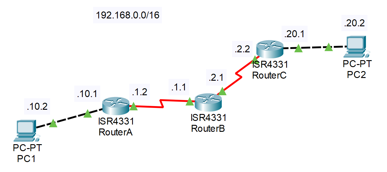
# 实验拓扑

# 实验过程
端口配置
Tip: 可以先修改各台路由器的 Hostname, 便于辨认.
配置 RouterA
// 切换到 g0/0/0(与 PC 相连) 的端口设置
RouterA(config)#int g0/0/0
// 配置 IP
RouterA(config-if)#ip address 192.168.10.1 255.255.255.0
// 启动端口
RouterA(config-if)#no shut

// 切换到 s0/1/0(与 RouterB 相连) 的端口设置
RouterA(config-if)#int s0/1/0
RouterA(config-if)#ip address 192.168.1.2 255.255.255.0
RouterA(config-if)#no shut
1
2
3
4
5
6
7
8
9
10
11配置 RouterB
// s0/1/0 与 RouterA 相连
RouterB(config)#int s0/1/0
RouterB(config-if)#ip address 192.168.1.1 255.255.255.0
RouterB(config-if)#no shut

// s0/1/1 与 RouterC 相连
RouterB(config-if)#int s0/1/1
RouterB(config-if)#ip address 192.168.2.1 255.255.255.0
RouterB(config-if)#no shut
1
2
3
4
5
6
7
8
9配置 RouterC
// s0/1/0 与 RouterB 相连
RouterC(config)#int s0/1/0
RouterC(config-if)#ip address 192.168.2.2 255.255.255.0
RouterC(config-if)#no shut

// g0/0/0 与 PC2 相连
RouterC(config-if)#int g0/0/0
RouterC(config-if)#ip address 192.168.20.1 255.255.255.0
RouterC(config-if)#no shut
1
2
3
4
5
6
7
8
9配置 PC1 和 PC2的 IP 地址和默认网关
参考实验指南快速开始的软件部分
用Ping命令测试各网段的连通性
PC1能连接RouterAC:\>ping 192.168.10.1 Pinging 192.168.10.1 with 32 bytes of data: Reply from 192.168.10.1: bytes=32 time<1ms TTL=255 Reply from 192.168.10.1: bytes=32 time<1ms TTL=255 Reply from 192.168.10.1: bytes=32 time<1ms TTL=255 Reply from 192.168.10.1: bytes=32 time<1ms TTL=255 Ping statistics for 192.168.10.1: Packets: Sent = 4, Received = 4, Lost = 0 (0% loss), Approximate round trip times in milli-seconds: Minimum = 0ms, Maximum = 0ms, Average = 0ms1
2
3
4
5
6
7
8
9
10
11
12
13同理,
PC2可以连接RouterC但
PC1无法连接PC2C:\>ping 192.168.20.2 Pinging 192.168.20.2 with 32 bytes of data: Request timed out. Request timed out. Request timed out. Request timed out. Ping statistics for 192.168.20.2: Packets: Sent = 4, Received = 0, Lost = 4 (100% loss),1
2
3
4
5
6
7
8
9
10
11路由表配置
建议对照上方拓扑图理解指令含义
指令:
ip route <目标网段> <子网掩码> <下一跳路由器地址(IP地址)>// 从 A 到 .20.0/24 要先经过 B (.1.1) RouterA(config)#ip route 192.168.20.0 255.255.255.0 192.168.1.1 // 从 C 到 .10.0/24 要先经过 B (.2.1) RouterC(config)#ip route 192.168.10.0 255.255.255.0 192.168.2.1 RouterB(config)#ip route 192.168.20.0 255.255.255.0 192.168.2.2 RouterB(config)#ip route 192.168.10.0 255.255.255.0 192.168.1.21
2
3
4
5
6
7
8完成路由表的配置后
PC1可以连接PC2C:\>ping 192.168.20.2 Pinging 192.168.20.2 with 32 bytes of data: Reply from 192.168.20.2: bytes=32 time=22ms TTL=125 Reply from 192.168.20.2: bytes=32 time=2ms TTL=125 Reply from 192.168.20.2: bytes=32 time=2ms TTL=125 Reply from 192.168.20.2: bytes=32 time=21ms TTL=125 Ping statistics for 192.168.20.2: Packets: Sent = 4, Received = 4, Lost = 0 (0% loss), Approximate round trip times in milli-seconds: Minimum = 2ms, Maximum = 22ms, Average = 11ms1
2
3
4
5
6
7
8
9
10
11
12
13尝试默认路由的配置
对于该实验的拓扑结构来说,只有 RouterA 和 RouterC 允许配置默认路由。
首先应该删除静态路由的配置,才配置默认路由。
以 RouterA 为例:
RouterA(config)#no ip route 192.168.20.0 255.255.255.0 192.168.1.1
RouterA(config)#ip route 0.0.0.0 0.0.0.0 192.168.1.1
1
2查看当前路由表
show ip route注:有*号表示默认路由
# 实验命令列表
| 指令 | 用法 |
|---|---|
| 路由表配置 | ip route [目标网段] [子网掩码] [下一跳路由器地址(IP地址)] |
| 删除静态路由的配置 | no ip route [目标网段] [子网掩码] [下一跳路由器地址(IP地址)] |
| 配置默认路由 | ip route 0.0.0.0 0.0.0.0 192.168.x.x |
| 查看路由表 | show ip route |
| 停止查看路由表 | no debug all |
# 实验问题
假如只分配了一个网段:192.168.10.0/24,你该如何搭建上述拓扑?请设计并加以实现。
← 03:交换机端口安全 05:动态RIP →